Technology
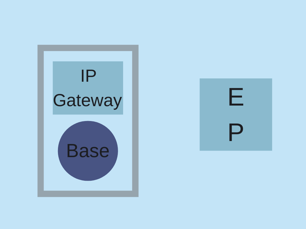
What differentiates Aurora Wireless Network’s technology is that every piece of the network from the sensor interfaces to the protocol was designed especially to provide the longest possible range and the highest energy efficiency practices for applications requiring low latency and modest data throughput. Networks covering multiple kilometers can be realized while also achieving multi-year endpoint battery life. Coverage can be enhanced with optional higher gain antennas and multiplied with network extenders. From one to hundreds of endpoints can be supported through a single IP connection. You are encouraged to read more by clicking on one of the boxes below:
Energy Efficiency
Energy efficiency has been carefully considered in the design of every part of an Aurora Wireless Network and especially for the endpoints:
- Optimized radio protocols minimize overhead.
- Sophisticated algorithms result in meticulous synchronization.
- Energy efficient transmitting and receiving components conserve battery life.
- Link budget intelligently adapts to your needs using only the energy necessary.
- Low leakage components eliminate waste.
- Precision power management prioritizes and swiftly detects and reacts to changing conditions.
A base and/or network extender may be powered from a small solar panel where USB or grid power is not convenient. The endpoints can be powered from coin cells, solar cells, or a single pair of AA Alkaline batteries that can last for up to several years as one of the multiple powering options.


(Energizer, 2005)

(Young, 2008)

(Energizer Battery Manufacturing Inc, 2008)
(Energizer Battery Manufacturing Inc, 2008)
Estimating Energy Needs
(Energizer Battery Manufacturing Inc, 2008)
- Quantity of real information that must be exchanged (there are often ways of minimizing the data transferred without compromising the information conveyed).
- Typical distance between base and endpoints and propagation conditions (pay attention to the relative heights of the respective antennas).
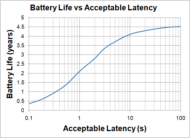
- The maximum latency acceptable (delay between when a message sequence initiated at one end of the link can be acted upon at the other end).
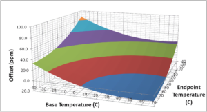
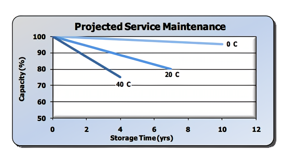
- Operating temperature (extreme temperatures degrade battery life depending on chemistry).
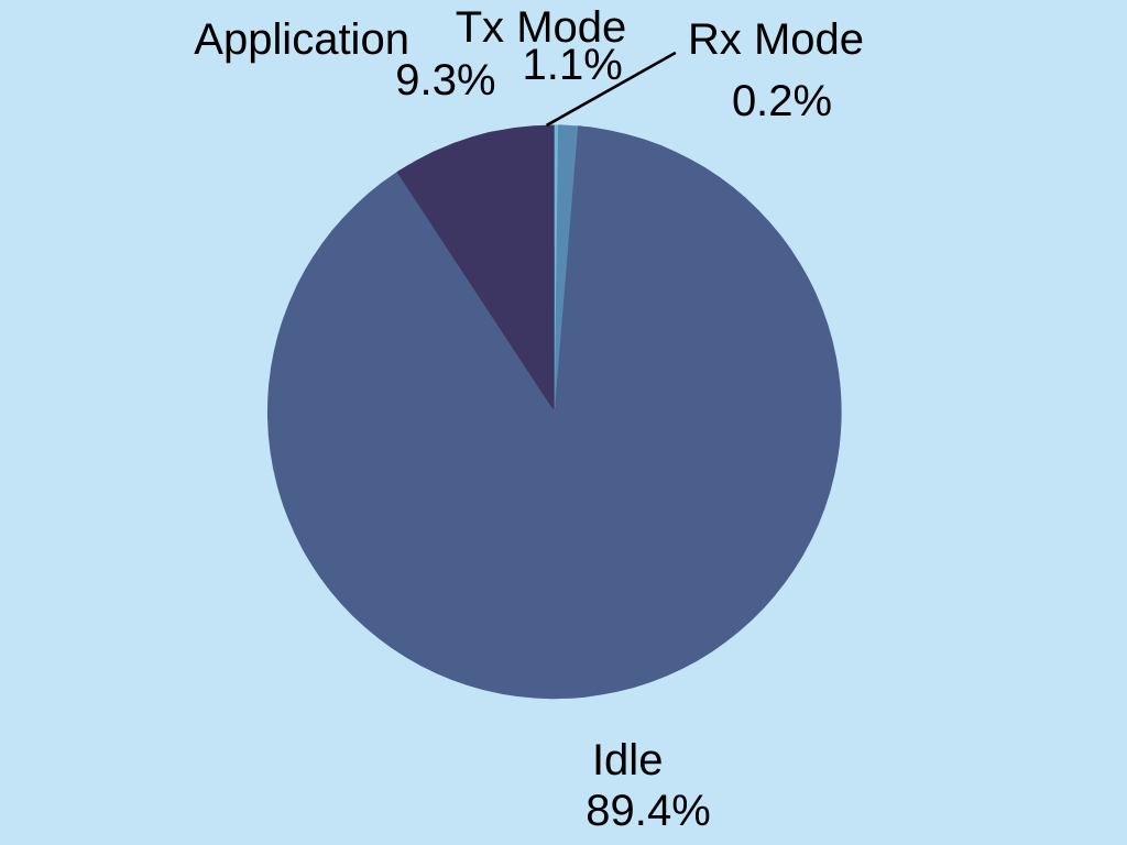
Energy consumption can be divided into three categories:
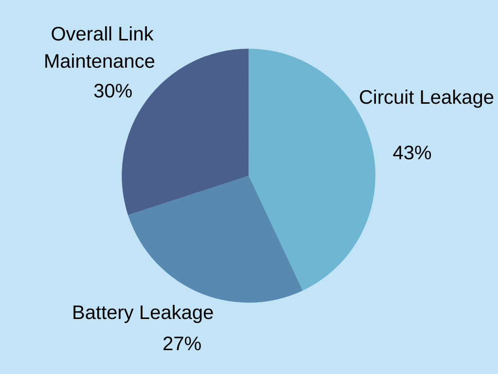
- Idle: This is the energy that does not directly contribute to receiving or transmitting messages. Factors include:
- Circuit Leakage (energy consumed simply because there is an applied voltage).
- Battery Self Leakage (batteries lose energy just sitting on the shelf).
- Link Maintenance (low latency requires always ON communication).
- Transmit: This is the energy consumed in transmitting the information. Factors include:
- The amount of data being shared (two-way communication allows you to share what you need and need what you share).
- Transmit power and efficiency (get the most power for the least energy).
- Packet overhead (eliminate excess bytes).
- RF output power (lower RF power means a dramatically longer battery life).
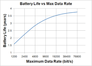
- Data rate (Higher bit rates results in dramatically less energy consumed).
The link automatically optimizes the data rate and transmitted power to your networks’ needs on an individual endpoint basis. The less data that you need to communicate the less energy will be consumed.
- Receive: Energy consumed in receiving information. Factors include:
- Receive efficiency (use the least energy possible in decoding the packet).
- Packet overhead (eliminate excess bytes).
- Synchronization precision (only use energy when you need to).
- Data rate (Higher bit rates results in dramatically less energy consumed).
- The amount of data being shared (two-way communication allows you to share what you need and need what you share).
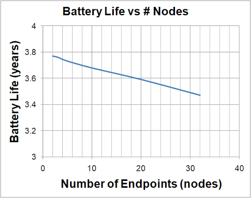
- The number of endpoints on the network.
Taking into consideration environmental factors the link automatically balances energy consumption against link reliability – using only as much energy as required to keep the link operating reliably.
Network Features
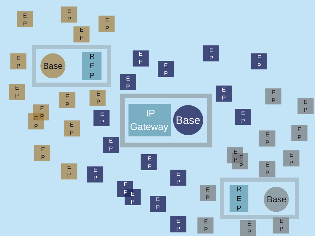
Your Aurora Wireless Network can be optimized to your requirements. There are three principle topologies to consider as you design your customized network.
Point to Point: In its most basic form, a base and endpoint communicate one on one. The base, as the “master”, usually initiates communication through a synchronized autonomous polling process however the endpoint can demand to be polled at any time. Communication can be once a day, every few seconds, or whenever needed but because the endpoint is always connected, latency is as low as one or two seconds.

Extended Network: In this configuration, the network can be expanded including mesh-like redundancy without significantly compromising the energy efficiency of the endpoints. In this way, an optimum solution can be achieved for many applications.
There are several reasons to incorporate network extenders. For example:
- You can expand your physical network coverage or extend your reach. Network extender endpoints join with conventional bases to form starlets. Starlets link to other starlets allowing your network to grow commensurate with your needs. With a reach of several kilometers per link, your network can get you from the base of one mountain range to the far side of another. By daisy-chaining multiple judiciously positioned network extenders ranges of 100 km or possible.
- You can enable a large number of endpoints to be accessed from a single host. Through a star and starlet approach, the number of endpoints within it can be multiplied.
- You can build in redundancy. If one base goes down, endpoints can readily attach themselves to another one in range and notify the host of their relocation.
Autonomous polls, hierarchical network activations, and super packets help make it easy and efficient to implement for modest data throughput applications.
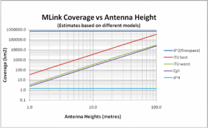
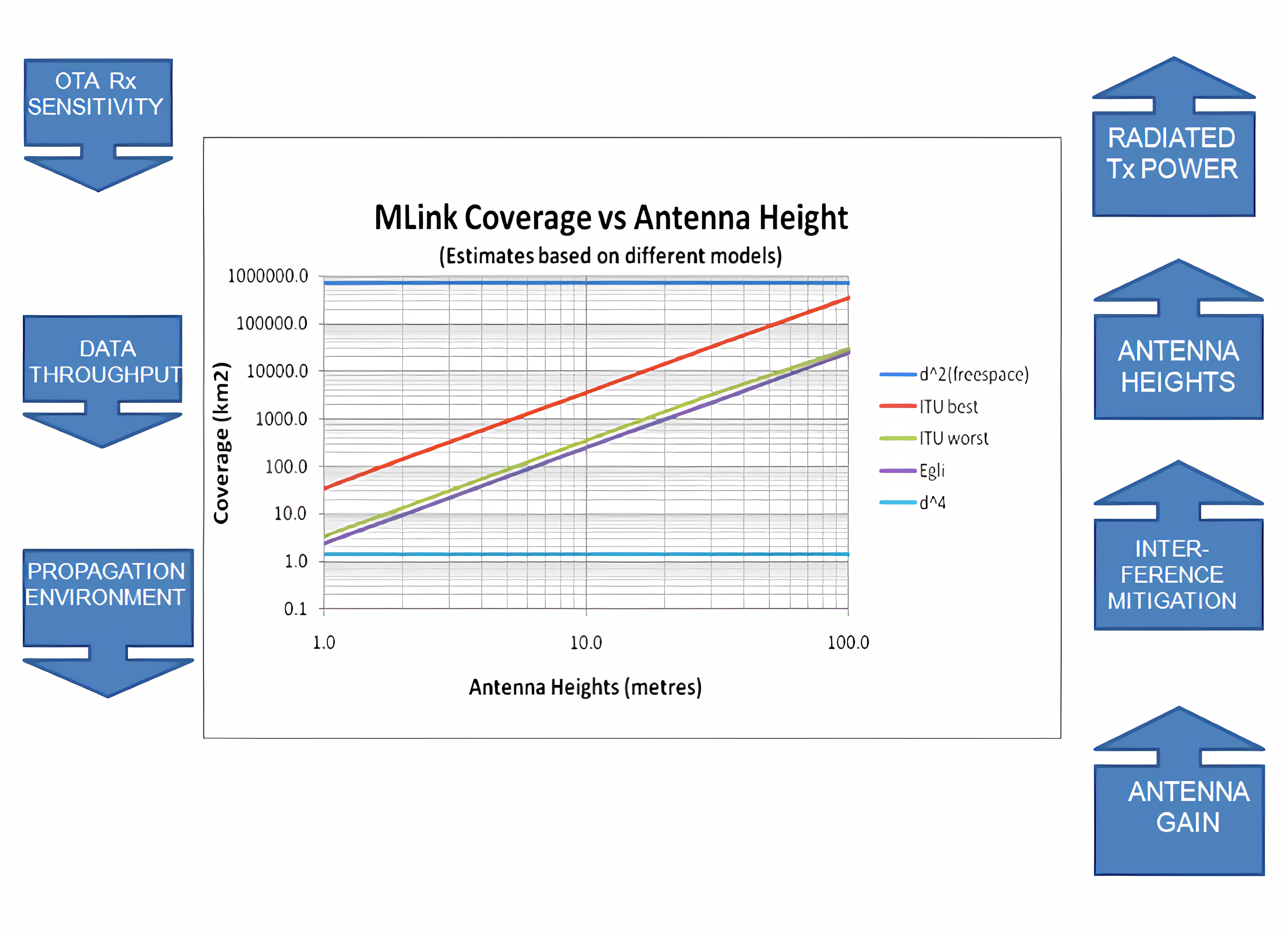
Radio Coverage
In estimating your potential radio coverage, a good place to start is the basic link budget. The link budget is a measure of the difference between the transmitted Radio Frequency power and the sensitivity of the receiver. The Aurora Wireless Network operates on a link budget of up to about 160 dB (optional external high gain antennas, lowest data rate, maximum output power). This is comparable to cellular (LTE). By comparison, Bluetooth is about 100 dB.
The actual range is dependent on many factors including, for example, antenna heights, propagation environment, and interference. You will likely find the following chart helpful.
In the videos below, you can see red navigation markers which are data points of locations where endpoints have continuously communicated their GPS information to the MLink. Of course, nothing substitutes for real field experience. Come with us on some rides around the city to get a feel for the coverage you might expect.
In this video, you can see the endpoints continuously transmitting their GPS information as the Aurora Wireless Networks team drive down 14 Street.
In this video, you can see the endpoints continuously transmitting their GPS information as the Aurora Wireless Networks team drive from Centre Street to downtown.
You can see the endpoints continuously transmit their GPS information while our team is in a moving vehicle.